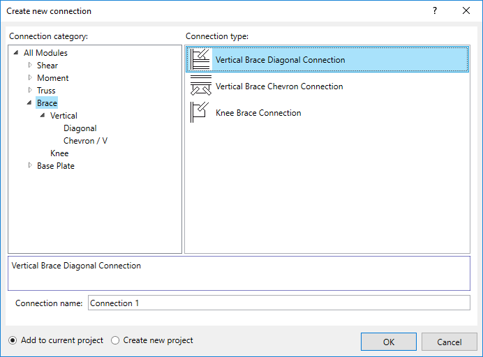
- Vertical Brace Diagonal Connection
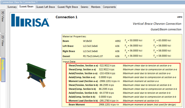
- Vertical Brace Chevron Connection
Design for seismic vertical brace connection detailing is done per the AISC Seismic Design Manual, 3rd Edition & 2nd Edition which contains the AISC 341-16/10 Seismic Provisions for Structural Steel Buildings.
The following seismic connections are available:
Note:
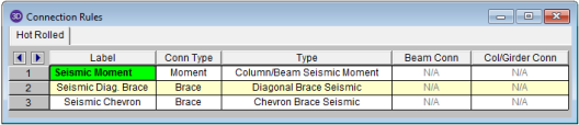
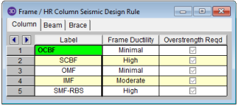
If you are using RISAConnection as a stand-alone program, then you can define your seismic vertical brace connection as follows:
If you are using the integration between RISA-3D and RISAConnection to create your model, then you can define your seismic connection as follows:
Determining the Seismic System
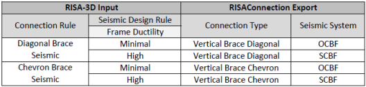
The integration between programs uses the following "translation" to determine the Seismic System:
Due to the nature of seismic brace design, the design loads for the connection are not always based on a load combination from RISA-3D. Therefore, the results for an integrated RISA-3D model will not report a governing load combination. Please see the Consideration of Input or Imported Loads section below.
Note:
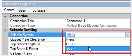
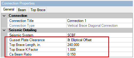
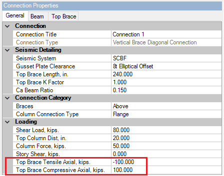
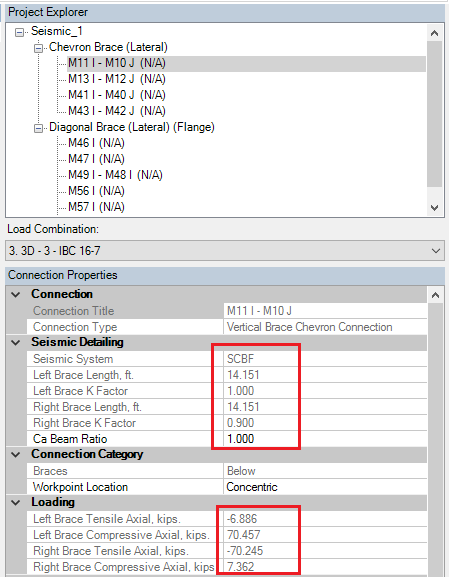
The following seismic input values are available for seismic vertical brace connections:
Below is a list of limitations regarding the seismic vertical brace design:
Seismic vertical brace connections must consider several possible envelops of loading. This is necessary in order to meet the following two requirements:
This complicated procedure makes seismic vertical braces unlike any other connection in the program. For RISA-3D integrated models this means that there is not always a governing load combination that controls the design. For stand-alone models, this means that the input brace loads are not always the governing loads used to design the connection.
First, the input (or RISA-3D imported) loads are compared to the expected brace strengths per the AISC 341-16. Depending on if the connection is an OCBF or a SCBF the governing design forces may be the calculated expected strength of the brace, rather than the input/imported loads. This comparison is displayed in detail in the Controlling Load Combination calculation on the Seismic tab of the results report:
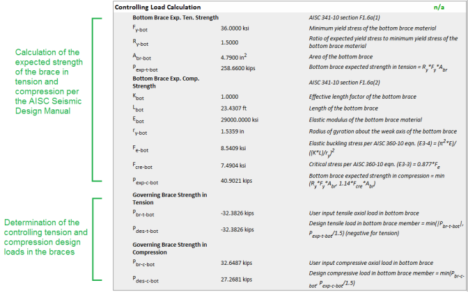
For more details on the specifics of this calculation, please see the OCBF and SCBF sections below.
Once the controlling brace loads in tension and compression are determined, the connection also must consider the application of these controlling loads to the connection in all possible cases (i.e. the connection must consider applied loading and opposite/reversible loading).
For OCBF frames, there are just two directions to consider. Because SCBF connections require both a pre- and post-buckling strength analysis, there will be four directions to consider. Please see the chart below for clarification. For more information on the two types of analyses (i and ii) for SCBF, please see SCBF Connection Strength, below.
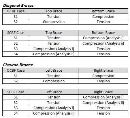
The applicable directional loading cases are reported in the Seismic Loading Combinations line of the Seismic tab of the results report.

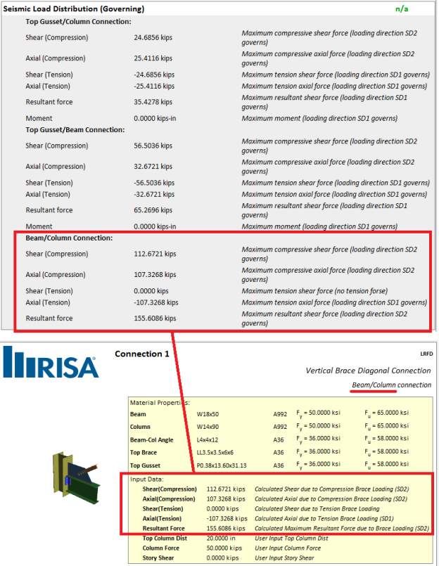
The loads at each sub-connection interface (gusset/column. gusset/beam, beam/column) are then calculated per the Uniform Force Method for each loading direction case. The full details of each of these calculations are shown in the Seismic Load Distribution Calculations on the Seismic tab of the results report.

Finally, the governing design forces at each sub-connection interface are reported in the Seismic Load Distribution Calc. (Governing) on the Seismic tab of the results report. The controlling case is reported in the description on the right. As you can see from this procedure, the governing loads at each interface do not necessarily all come from the same load combination (for integrated models) or even directional load case.
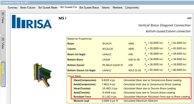
These are the same forces that you will see reported in the yellow box at the top of each sub-interface tab in the results report.
Each sub-connection interface is then checked for all limit states (tension and compression) per these governing design loads. If a limit state applies to both tension and compression loading, it will be checked against the largest demand value.
AISC Seismic Provisions for Structural Steel Buildings (AISC 341-16) chapter F1 gives the design requirements for designing OCBF seismic brace connections.
Per AISC 341-16 section F1.6a, the required design strength of an OCBF brace connection shall be the load from the governing overstrength load combination. Per the exception, this does not need to exceed the expected strengths in tension (section F1.6a(a)) or the expected strength in compression (F1.6a(b)). Exception on oversized holes (F1.6a(c)) is not currently considered.
Therefore, in RISAConnection, the governing design load (in tension or compression) is calculated as the minimum of the expected strength of the brace and the user-input brace axial load.
These calculations are shown in detail under the Controlling Load Calculation check on the Seismic tab of the results report.
AISC Seismic Provisions for Structural Steel Buildings (AISC 341-16) chapter F2 gives the design requirements for designing SCBF seismic brace connections.
Per AISC 3410-16 section F2.3, we are required to consider the following two analyses of the connection:
RISAConnection considers these analysis methods in the load cases. The design strength used for each load case is described below.
Design Tensile Strength
Per AISC 341-16 section F2.6c(1), the required tensile strength of a SCBF brace connection shall be the expected strength in tension .
Although AISC 341-16 section F2.6c(1)(b) says that the required tensile strength may come from the maximum load effect indicated by analysis, RISAConnection does not allow input axial loading to override the calculated expected strength in tension per F2.6c(1)(a). This is because the analysis methods specifically stated by the code (see Commentary to section F2.6c(1)) are not possible with RISA products. Therefore, the program always designs to the full expected yield strength in tension.
Design Compressive Strength
Per AISC 341-16 section F2.6c(2), the required compressive strength of a SCBF brace connection shall be taken as 1.1 times the expected strength in compression for LRFD or (1.1/1.5) times the expected strength in compression for ASD. Therefore, in RISAConnection, the governing design compressive load is calculated as the following:
These calculations are shown in detail under the Controlling Load Calculation check on the Seismic tab of the results report.
Note:
In addition to the procedures and provisions listed above, the following assumptions are considered when checking seismic vertical brace connections.
For diagonal brace connections where there is only one brace (either above or below), the program will calculate the controlling brace design force in tension and the controlling brace design force in compression.
Then, the program will calculate the associated forces at each sub-connection interface. This is done considering multiple loading cases to account for the various combinations of possible loading on the connection. Please see the chart above for a detailed description of the various directional load cases that RISAConnection will consider.
The sub-connection limit states will then be checked against the governing tension and compression forces from each of the possible loading cases.
Note:
For brace connections with two braces (either chevron connections, or diagonal braces with two brace members) the program will calculate the controlling brace design force in tension and the controlling brace design force in compression for each brace.
Then, the program will calculate the associated forces at each sub-connection interface. This is done considering multiple loading cases to account for the various combinations of possible loading on the connection. Please see the chart above for a detailed description of the various directional load cases that RISAConnection will consider.
The sub-connection limit states will then be checked against the governing tension and compression forces from each of the possible loading cases.
Note:
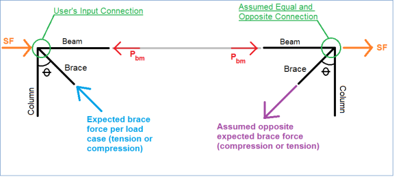
When calculating forces at the Beam to Column sub-connection interface in a vertical diagonal brace, the program considers the beam axial and shear forces as part of the summation. Due to the fact that RISAConnection is running multiple load cases of possible loading, we cannot rely on the user-input Beam Axial Load for this calculation. Therefore, RISAConnection utilizes an approximate method used in AISC Seismic Design Manual example 5.3.5 (see page 5-158).
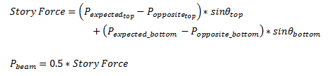
This method assumes that the connection is part of a frame which has an equal and opposite connection across from it. Using the brace forces calculated in the Controlling Load Calculation, RISAConnection will calculate the beam axial force at the connection as half of the Story Force in the frame. The details of this calculation are included in the Seismic Load Distribution Calc. for each directional load case.
Note:
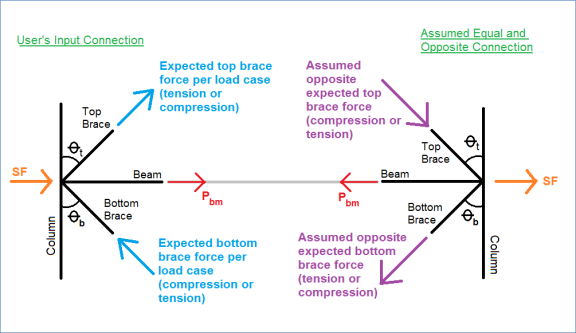
The calculation is based on simple geometry. Details for each case are shown below.
Single Brace Member

Two Brace Members
After the governing forces are determined, using the methods discussed above, the governing forces will be reported on each sub-connection tab of the results report.

Because seismic vertical braces design for both tension and compression forces, the resulting limit states will include both tension and compression checks. If any check is designed for both tension and compression loading, the limit state will be checked against the maximum calculated load.
Notes:
The following seismic checks are included on the Seismic tab of the report.
This "check" presents the details of the calculations which determine the brace design forces.
This "check" presents the details of the appropriate loading directions.
Seismic Load Distribution Calculations (Loading Direction XX) -
This "check" presents the details of load distribution per the brace design loading direction XX.
Seismic Load Distribution Calculations (Governing) -
This "check" presents the governing loads at each sub-connection interface per all applicable loading directions.
This checks ensures the code requirements in AISC 341-16 section D2.2(b) which says that "bolts and welds shall not be designed to share force in a joint". OCBF and SCBF vertical diagonal brace connections must have either all bolted or all welded connections.
Seismic Workpoint Limitations-
This check verifies that the connection is a concentric brace connection by limiting the workpoint eccentricity to an arbitrary threshold of dbeam/10. If the workpoint eccentricity exceeds this limit, the check will fail which means the connection does not meet the requirements of AISC 341-16 section F1.2 or F2.2 which says that seismic brace design is only applicable to concentric vertical brace connections.
Seismic Yield Stress Limitations -
This check includes material geometry limits from the AISC 341-16 section A3.1.
This check includes slenderness limits from the AISC 341-16 section F1 for OCBF and section F2.5b for SCBF.
Seismic Width to Thickness Ratios-
This check includes width to thickness ratio checks per AISC 341-16, Table D1.1.
This check is only applicable to SCBF braces that are slotted over the gusset plate. The check calculates the amount of additional reinforcement that must be added to the brace in order to ensure that the brace has significant strength to resist the high expected loads (see AISC 341-16 section F2.5b(c)). The calculation procedure is based on that found in example 5.3.8 of the AISC Seismic Design Manual (page 5-232).
At this time, the program only reports the amount of reinforcement that must be added. A later version will include the option to add reinforcing bars to the connection.
This check includes plate thickness check per AISC 341-16 section F2.6b(a) which accounts for the check against rotational ductility requirements. Page 5-122 of the AISC Seismic Design Manual says that simple connections per Part 10 of the AISC Steel Design Manual meet this requirement. Therefore, this check is done to the requirements of Part 10. This is only applicable to SCBF connections.
Seismic Gusset Rotation Capacity/Clearance-
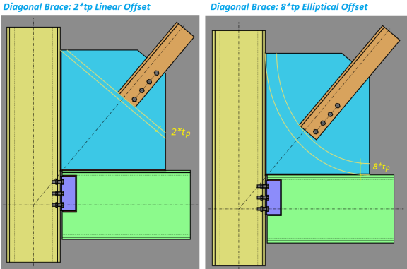
Per the User Note in AISC 341-16 section F2.6c(3)(b), accommodation of inelastic rotation is typically accomplished by terminating the brace before the line of restraint. The commentary on this section suggests a 2t linear offset. This check includes verification of this suggested geometry. This is only applicable to SCBF connections.
Page 5-338 of the AISC Seismic Design Manual (and many other technical references) suggest using an elliptical line on vertical brace connections to achieve a more compact gusset plate. Instead of the 2*tp Linear option, you may select the 8*tp Elliptical method for SCBF vertical brace connections. This option is available with the Seismic Input parameters.
Note:
RISAConnection checks to make sure that the hinge line distance is between 2*tp (the lower limit suggested by the AISC 360-16) and 4*tp (an upper limit suggested in the Steel Tips article "Seismic Detailing of Gusset Plates for Special Concentrically Braced Frames" by Astaneh-Asl, Cochran, and Sabelli.
When the 8t Elliptical option is selected, this limit state will check to verify that the hinge line distance is 8*tgusset or greater from the elliptical hinge line.
Note:
The hinge line will be displayed in yellow on the 2D View of the connection.
![]()
Per page 5-357of the AISC Seismic Design Manual, interface welds at the gusset to beam and gusset to column connections should be designed for the expected tensile strength of the gusset plate. Therefore the Required load for this check will always be equal to Ry*Fy*tplate. This is only applicable to SCBF connections.
In addition to the regular DXF output, the seismic connections will include: